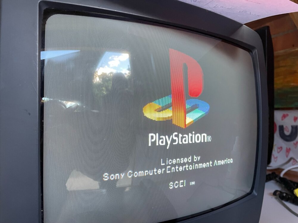
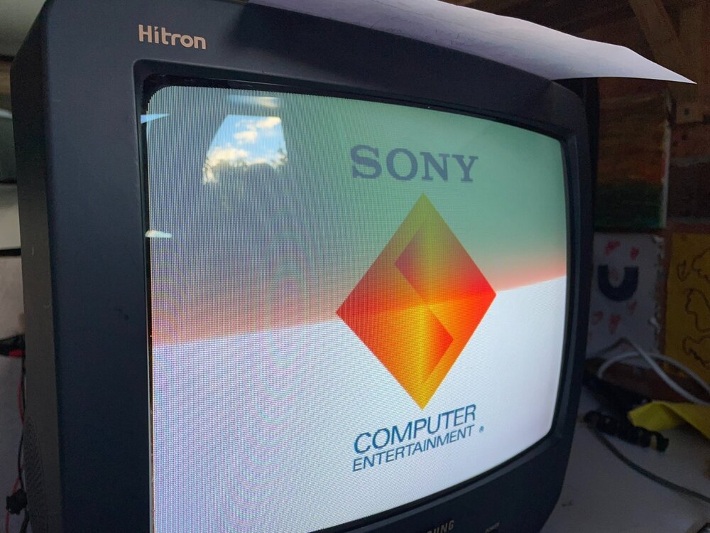
Samsung TV-348 Hitron (the Aussie 14″ version) was my first ever TV I bought in Australia after moving here in 2000. Therefore, it is a special set for me and I was determined to re-obtain it after I got rid of it some years ago.
When I finally found and purchased it, the next logical step was to attempt to RGB mod it as I was already deep into retro gaming and PCs business.
This specific to Australian market TV has a S15A chasis and TDA 8841 jungle chip.
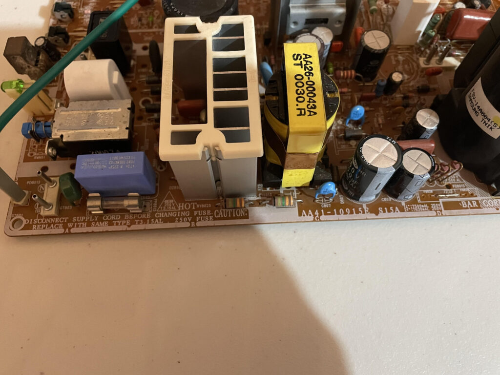

Being made for an Australian market, it comes with only composite inputs (on the front and on the back)… no scart nor s-video.
Samsung produced LOTS of same looking TVs with the same shell for different markets. Some had scart some not depending on the country. A few different chasises were used for these TVs around the world. The Australian version of this TV was slightly different from the rest…well at least according to my inability to find exact schematichs for it. I ended up using schmatics for a slightly different model but it was close enough.
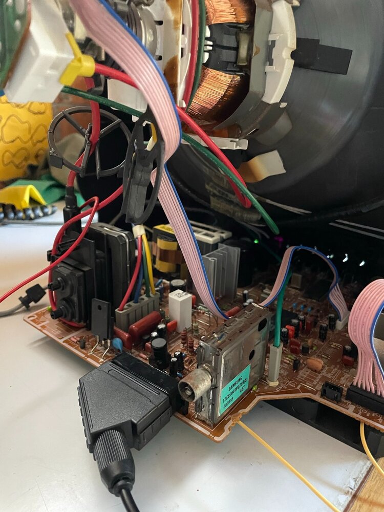
The approach for the RGB mod is to remove the existing composite socket assembly, replace it with the same form factor SCART assembly and add the missing components related to RGB input to the chasis . The TV’s chasis was designed to accomodate both composite and SCART connectors.

RGB socket
- Remove/desolder the Composite ports assembly from the chasis on the back of the TV
- Install/solder the Scart port instead (I used the following one and it fit perfectly… variation with the legs)

RGB mod
- Fill in the missing parts on the chasis including:
- 0.1uF (100nF) capacitors (C253, C254, C255)
- For simplicity: add 75R resistors for R, G and B lines in DZ701, DZ702 and DZ703.
I went through the schematics and found missing (in red) components on the chasis. Green circles are the components that I found on the chasis.

Blanking
It looks like instead of RW702 there is space for an unused R704 (not on the list of any schematics for this chassis that I had). It connects the pin 16 (same as RW702 would have) and 18, 21… (ground) of scart.
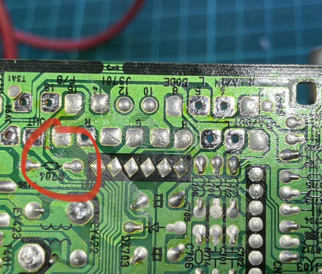
- Pin 16 just needs a 75R to ground and then you need to make sure it’s making its way to the Jungle FB pin -> Add a 75R resistor to ground (R704)
- If you want to fully rebuild the circuit, you will need:
- Transistor Q703 (KSA539-Y)
- R705 330R
- R703 1KR
- D701 1N4148
- R251 1KR
- If you do not want to rebuild the circuit you can just jumper straight from R705 to D701 and it should be enough (I did this and it worked fine).
Service manu changes
So the reason we are doing this is to let the TV know to “enable” RGB/SCART on the jungle chip. To do is we need to set a “country” to any country that uses SCART as a standard: “France”, for instance.
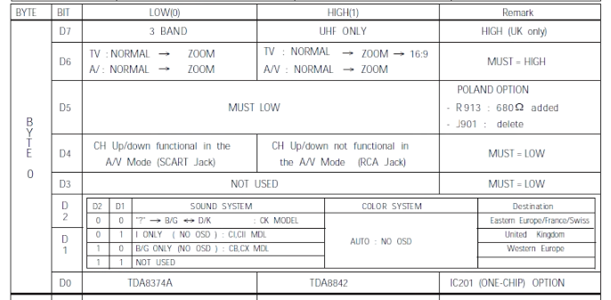
This is done by setting Byte/Bits settings in service menu.
Some remotes (like mine) won’t a P.Std button. In this case use “Menu” button instead.
- Enter service menu: Standby > Display > Menu (or P.Std) > Mute > Power
- Byte 0 option’s but D4 must be set to 0 (Low) in order to enable Scart. In my case, it was 40 which means D4 of Byte 0 was already set to 0

Voltage for blanking
Need a 33K/24K resistor voltage divider for Scart’s pin 8 to replicate RW701 (my RW701 was fully empty).
What I did was:
- Install a 33K resistor between pins 2 and 3 of RW701
- Install a 24K resistor in DZ705
This reduced the 12V on pin 8 of Scart down to 5V.
In all the schematics I found for a similar chassis they incorrectly drew the pair (They had it first 24K R and then 33K R – we want it reversed for the 5V on the exit of this divider)
In order to divide the voltage you want to have the Scart pin 8 (which will be 12V) come into the TV, then go through a 33K resistor and then have the 24K resistor connected to ground. (calculation is 24/(24+33)*12=5.05V.
Tweaks on the flyback transformer
After my install, I had to tweak the flyback transformer:
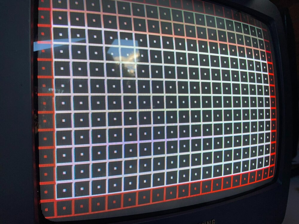
- Brightness: my brightness became WAY too high. The black was grey and I saw the stationary retrace lines. After turning the brightness knob it was all good
- Sharpness: turned sharpness knob to make it sharper
Extra notes
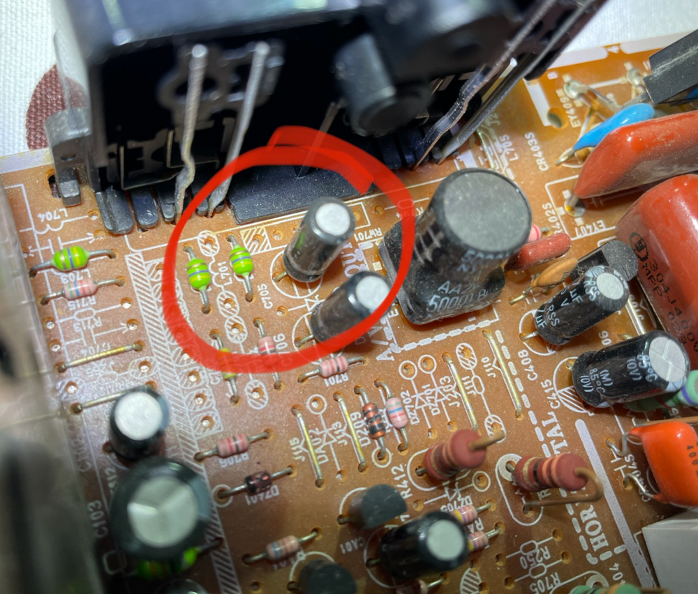
- The Audio circuitry is likely already in place but you can add the missing components pictured below to make it do a stereo to mono mix. (R713, L704, C704)
- Don’t worry about the resistor arrays (RW701 and RW702), instead need to install “equivalent” circuitry….
- I omit the zener diodes DZ701, DZ702 and DZ703. Instead I put the75R termination resistors in those positions. That takes care of most of RW701. If you really want to add the zener diodes they could share the holes with the 75R.
- To take care of Scart Pin 16 and RW702 you just need to make sure the circuit for pin 16 has a 75R to ground. Can possibly do that using the holes in the header for RW702.


Special thanks
I would like to express my special thanks to buttersoft and MarkOZLAD from https://www.aussiearcade.com/ who helped me greatly in my journey of RGB modding this set.
Other related to similar task threads can be found on AussieArcade:



Leave a Reply